Hola compañeros,
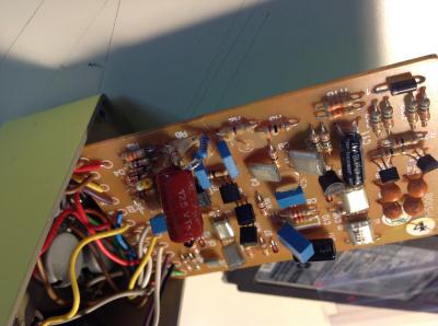
Me he puesto manos a la obra en modificar elste pedalillo. Un Taiwan. Si existe un hilo no lo he encontrado..... Puede ser interesante meterle mano ya que se dice que su circuito se asemeja al mitico ts9.
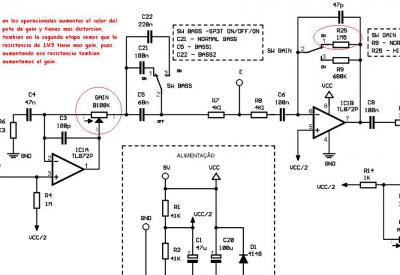
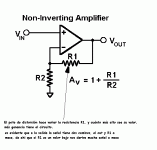
Empiezo aportando la doc que estoy siguiendo....... De momento he modificado los condensadores, esperando un mejor rendimiento de bajos.
Adjunto,
Modifications
Now, let's take a look at the modifications that I performed on my pair of SD1s. These mods are based on Robert Keeley's "5-Star Germanium" mods, but I made a couple of changes and omissions. HERE is a schematic that has the changed components highlighted in red. And below is a table that lists all the changes made to the circuit.
Component Number Original Part New Part
C2 18 nF 100 nF Metal Film
C3 47 nF 100 nF Metal Film
C7 1 µF Electro. 1 µF NP* Metal Film
C8 47 nF 100 nF Metal Film
C10 1 µF Electro. 1 µF NP* Metal Film
D6 1N4148 Silicon 1N34A Germanium
LED 3mm Red LED 3mm White Super Bright LED
R2 470K, 5% Carbon Film 620K, 1% Metal Film
R6 4K7, 5% Carbon Film 2K2, 1% Metal Film
R30 3K9, 5% Carbon Film 1K, 1% Metal Film
U1 JRC4558DD Burr Brown OPA2134PA
* NP = Non Polar
These modifications add a great deal to the audio quality of the circuit. You can get a little creative when choosing a new OPAMP for your SD1. The normal choices are the original JRC4558DD, the Texas Instruments RC4558P, the Burr Brown OPA2604AP, the Burr Brown OPA2134PA, and even the Texas Instruments TLC2272ACP, which is a linear CMOS OPAMP. I chose the Burr Brown OPA2134PA because it's designed specifically for audio applications, and because it's super high quality and low noise. The Burr Browns aren't cheap though... the OPA2134 was about $2.50 for a single one and the OPA2604 is $3.50 for a single one. So here's what we're doing with the rest of the SD1's circuit:
Changing C2, C3, and C8 to 100 nF will increase bass response.
Changing C7 and C10 to 1 µF NP metal film will remove some harshness from the circuit.
Changing D6 from a 1N4148 Silicon diode to a 1N34A Germanium diode will help to further increase the distortion.
Changing R2 to 620K will increase the input impedance of the input buffer resulting in more clarity when the pedal is in effect more or when it's bypassed.
Changing R6 to a 2K2 will increase the amount of avalible overdrive.
Changing R30 from 3K9 to 1K will increase the current being supplied to the LED, therefore increasing the brightness of the new LED, but it will also put more of a hurt on the battery, if you use one.
Changing the original not-so-bright 3mm red LED won't do anything for the sound, but putting that 3mm water clear super bright white LED in there will certainly make the pedal look a little more "trick."
Some Final Points
If you own an older SD1, there will be a diode and resistor on the circuit board, D3 and R31 (not shown on the schematics), that are connected to the negative pin of the DC power jack. I would recommend that you remove these two components from the circuit board and replace them with jumpers. Doing this will increase the power being delivered to the circuit so that it will have even more "oomph." If you own a newer SD1, then these two components are already replaced with jumpers, so you won't have to worry about them.
Saludows!!


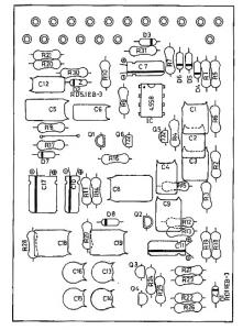

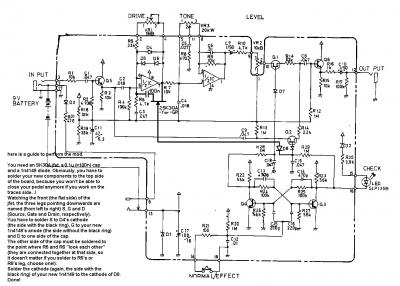
 revisare los comunes ya que en otro BOSS que modifique, el tierra lo tuve que soldar yo de nuevo. Los modelos taiwan no llevan dicho cable, se pasa por el chasis y puede dar problemas.

 comprare unos switches..... y como tengo algo de tiempo voy a seguir con el.

 nada tienes que perder.
 cualquier opinion me será seguro de ayuda